
About ARP Bolts
![]()
They say that to be successful you must identify a need and satisfy it. Back the early 1970s, racing enthusiast Gary Holzapfel saw that many of his friends’ broken engines were caused by fastener failure.
At the time, there were no commercially available studs and bolts up to the challenge. So Holzapfel called upon his many years of fastener making experience for a leading aerospace subcontractor and founded ARP (Automotive Racing Products).
In the ensuing years, the firm has grown from what was literally a backyard garage workshop into a highly diversified manufacturer with seven operational entities in Southern California with a combined area in excess of 200,000 square feet. These include forging, heat-treating, machining, quality control finishing and packaging/warehousing facilities in Santa Paula and Ventura, California.
There is even a unique racing-themed restaurant at the main Santa Paula facility - called “ Hozy’s Grill” - which is open to the public.
Today, ARP’s product line contains thousands of part numbers, and has expanded to include virtually every fastener found in an engine and driveline and throughout the suspension and frame. These range from quality high performance OEM replacement parts to exotic specialty hardware for Formula 1, IndyCar, NASCAR and NHRA drag racing and marine applications.

The design of automotive bolts is a complex process, involving a multitude of factors. These include the determination of operating loads and the establishment of geometric configuration. The process for connecting rod bolts is described in the following paragraphs as an example.
The first step in the process of designing a connecting rod bolt is to determine the load that it must carry. This is accomplished by calculating the dynamic force caused by the oscillating piston and connecting rod. This force is determined from the classical concept that force equals mass times acceleration. The mass includes the mass of the piston plus a portion of the mass of the rod. This mass undergoes oscillating motion as the crankshaft rotates. The resulting acceleration, which is at its maximum value when the piston is at top dead center and bottom dead center, is proportional to the stroke and the square of the engine speed. The oscillating force is sometimes called the reciprocating weight. Its numerical value is proportional to:
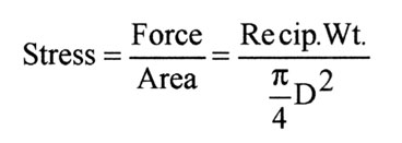
It is seen that the design load, the reciprocating weight, depends on the square of the RPM speed. This means that if the speed is doubled, for example, the design load is increased by a factor of 4. This relationship is shown graphically below for one particular rod and piston.
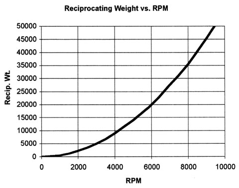
A typical value for this reciprocating weight is in the vicinity of 20,000 lbs. For purposes of bolt design, a “rule of thumb” is to size the bolts and select the material for this application such that each of the 2 rod bolts has a strength of approximately 20,000 lbs. (corresponding to the total reciprocating weight). This essentially builds in a nominal safety factor of 2. The stress is calculated according to the following formula:
so that the root diameter of the thread can be calculated from the formula:
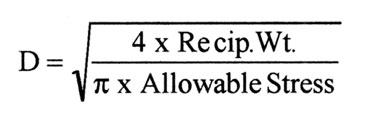
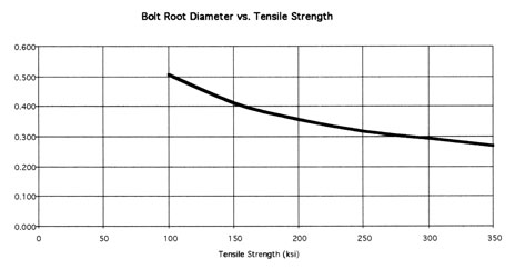
This formula shows that the thread size can be smaller if a stronger material is used. Or, for a given thread size, a stronger material will permit a greater reciprocating weight. The graph shows the relationship between thread size and material strength.
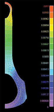
It must be realized that the direct reciprocating load is not the only source of stresses in bolts. A secondary effect arises because of the flexibility of the journal end of the connecting rod. The reciprocating load causes bending deformation of the bolted joint (yes, even steel deforms under load). This deformation causes bending stresses in the bolt as well as in the rod itself. These bending stresses fluctuate from zero to their maximum level during each revolution of the crankshaft.
The next step is to establish the details of the geometric configuration. Here the major consideration is fatigue, the fracture that could occur due to frequent repetition of high stresses, such as the bending stresses described above. Several factors must be considered in preventing fatigue; attention to design details is essential.
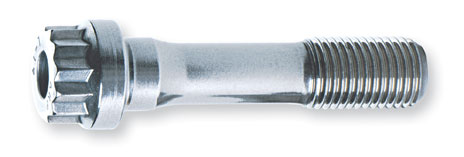
Fatigue failure is frequently caused by localized stress risers, such as sharp corners. In bolts, this would correspond to the notch effect associated with the thread form. It is well known that the maximum stress in an engaged bolt occurs in the last engaged thread. By removing the remaining, non-engaged threads, the local notch effect can be reduced. This leads to the standard configuration used in most ARP rod bolts: a reduced diameter shank and full engagement for the remaining threads. Providing a local fillet radius at the location of the maximum stress further reduces the local notch effect. Thus this configuration represents the optimum with respect to fatigue strength.
The reduced diameter shank is helpful in another sense. It reduces the bending stiffness of the bolt. Therefore, when the bolt bends due to deformation of the connecting rod, the bending stresses are reduced below what they would otherwise be. This further increases the fatigue resistance of the bolt. A typical bolt configuration is shown below.
Once the bolt configuration has been established, the manufacturing process comes into play. This involves many facets, which are discussed in detail elsewhere. Here, however, one process is of primary interest. With respect to bolt fatigue strength, thread rolling is a major consideration. Threads are rolled after heat treating. This process, which deforms the metal, produces a beneficial compressive stress in the root of the thread. It is beneficial because it counteracts the fluctuating tensile stresses that can cause fatigue cracking. If heat-treatment were to occur after rolling, the compressive stresses would be eliminated. This would therefore reduce the fatigue resistance of the bolt.
An additional factor must be taken into account in defining the bolt configuration: the length of engaged thread. If too few threads are engaged, the threads will shear at loads that are lower than the strength of the bolt. As a practical matter, the thread length is always selected so that the thread shear strength is significantly greater than the bolt tension strength.
This problem is especially important in bolts used in aluminum rods because of the fact that the shear strength of aluminum is much lower than the shear strength of steel.
Finally, although not a design parameter, the subject of bolt installation preload must be addressed. It is a fundamental engineering concept that the force in a bolt in an ideal preloaded joint will remain equal to the preload until the externally applied force exceeds the preload. Then the force in the bolt will be equal to the external force. This means that fluctuating external forces will not cause fluctuating forces in a preloaded bolt as long as the preload exceeds the external force. The result is that fatigue failure will not occur.
In a non-ideal joint, such as in a connecting rod, the bolt will feel fluctuating stresses due to fluctuating rod distortions. These are additive to the preload, so that fatigue could result. In connecting rods, precise preloads are required because if they are too low, the external forces (the reciprocating weights) will exceed the preloads, thus causing fatigue. If they are too high, they provide a high mean stress that combines with the fluctuating stresses due to rod distortion. Again, fatigue is promoted. The objective, then, is to preload a bolt so that it just exceeds the external load, and no higher.
To sum up: both insufficient preloads and excessive preloads can lead to fatigue failures.
Appropriate preloads are specified for each ARP bolt. These preloads can be attained in a connecting rod by applying proper torque using a torque wrench or by measuring the amount of stretch in the bolt using a stretch gauge (it is known that a bolt stretches in proportion to the tension in it). The torque method is sometimes inaccurate because of the uncertainty in the coefficient of friction at the interface between the bolt and the rod. This inaccuracy can be minimized by using the lubricant supplied by ARP.
Other factors, equally as important as design, include material selection, verification testing, processing, and quality control. These aspects of bolt manufacturing are discussed elsewhere in this document.
The foregoing discussion concentrated on the design of bolts. The same considerations apply in the design of studs.